|
Optilux
Lighting Control and Regulation System
System Overview
Product Types: Optilux Controller
Product Ref:
OPL01 6 – 10 KVa Controller 1 Phase
OPL02 6 - 10KVa Controller 3 Phase
Product Description:
The
Optilux Lighting Control and Regulation System has been specifically developed
for use with discharge lighting in large exposed areas such as Airport Car Parks or Sea Ports.
Its advantage over similar products is that the Optilux System forms part of the
Insight range of wireless proximity controls, allowing the lighting to be maintained at a constant level as long as an area
is occupied. This is of particular significance in Seaports where lighting levels in working areas are strictly controlled
and normal regulation equipment would not be suitable.
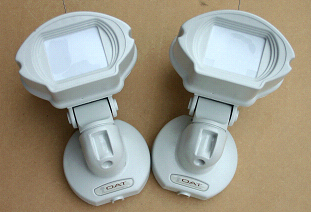
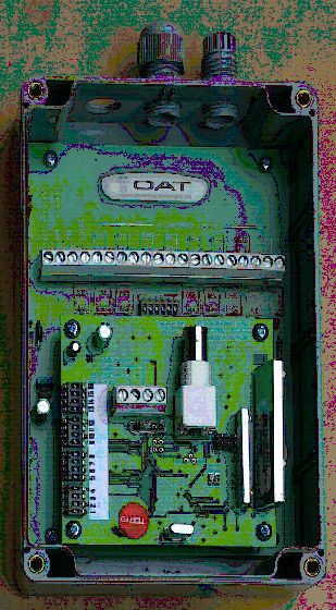
The
Optilux Controller has been designed to meet the most demanding criteria encountered
in an external lighting environment. The product is provided mounted on a back plate that is either fitted into a purpose
built IP65 control panel by OAT or installed within the Clients’ own feeder pillar, space permitting. The product is
available in 2 sizes that are both three phase units as standard, although larger units and single phase units can be made
to order.
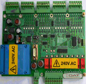
The rationale
behind the system is to save energy whilst still providing adequate lighting levels as and when the areas are occupied. The
methodology of the energy saving techniques is based on a voltage reduction unit that controls the lighting levels based upon
parameters preset within the unit. This system will operate in conjunction with a wireless network of proximity sensors that
will control the output of the voltage reduction unit according to the occupancy levels of the areas to be controlled.
The Voltage
Reduction unit is controlled from four sources:
- A photocell operating the lights at night once threshold of darkness has been met
- One of a number of wireless PIRs that will operate the lights to a preset voltage once occupancy
has been detected
- An On/Off/Auto override key switch
- A Time clock override
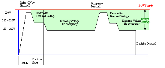
Upon initial operation as dictated
by the photocell, the controller provides a 230V AC signal to the lights in order to initiate the striking arc and turn the
lamps on. After a time period of 5 minutes, the voltage is reduced to a nominal voltage of between 210 and 220V AC (settable
either via a potentiometer) in order to maintain nominal light levels. The initial output voltage of 230v AC shall be fixed
regardless of the incoming supply voltage as long as this is higher than 230 V AC.
A system of wireless PIRs provide
a volt free input to the Controller. After a time period of 10 minutes to 1 hour (adjustable), assuming no occupancy has been
detected, and then the voltage supplied to the lamps is further reduced to a minimum of 180V (adjustable via a potentiometer)
up to 210V AC.
Upon detection of occupancy by
means of the wireless PIR network, then the controller shall react as if it has been operated by a photocell, i.e. the voltage
is ramped to a maximum of 230V AC and then reduced to nominal, followed by a further reduction to the economy setting of between
180 and 210 V AC.
The On/Off/Auto
key switch provides the facility to override the control system as required, whilst the inbuilt time switch provides the facility
to disable the lights during preset times.
The controller
is configured so that regardless of incoming voltage fluctuations, the outgoing voltage to the system will always be constant
wherever in the control cycle the system maybe.
The control of the system is affected by means of an electronic programmable system either with fixed variables
or software settings. The microprocessor monitors the input and output variables constantly. In the event of a fault occurring,
the system shall revert to a failsafe mode whereby the voltage reduction unit is bypassed by means of a suitably rated contactor
and the lights are fed with the full system voltage. In the event of a fault, a warning light is illuminated on the PCB or
panel facia.
Summary of Operation
|